Step Bends
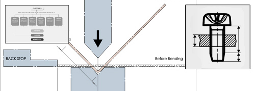
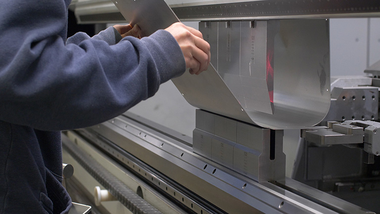
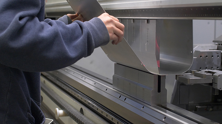
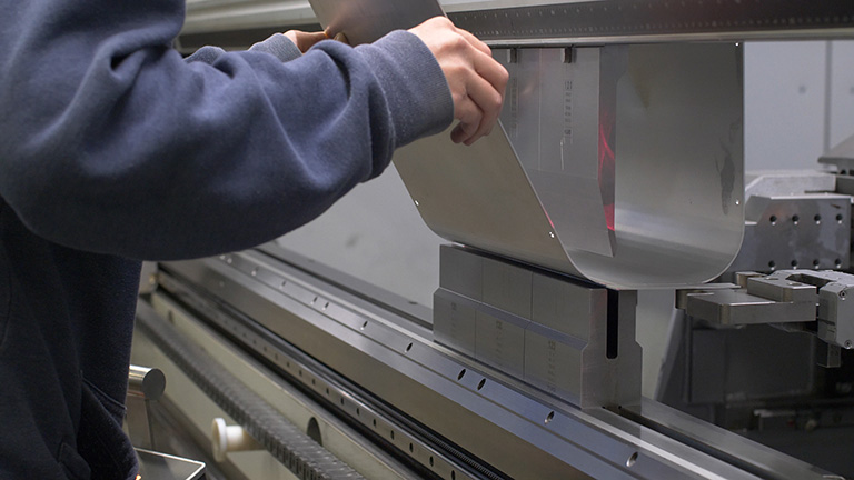
In sheet metal fabrication, bending is the critical operation for creating the custom parts required. Our Sheet metal is bent with a press brake or folder in order to form custom electronic enclosures and parts.
Any metal that is bent will have a radius along the inside of the bend. We are able to achieve very small bend radii, as small as 0.04” or 1.02mm (view our Bend Radii & Minimum Bend Sizes resource for more information). However, we are also able to create very large bend radii through a process called step bending.
If your project requires enclosures or parts with a very large bend radius, we can achieve your vision.
Step Bending
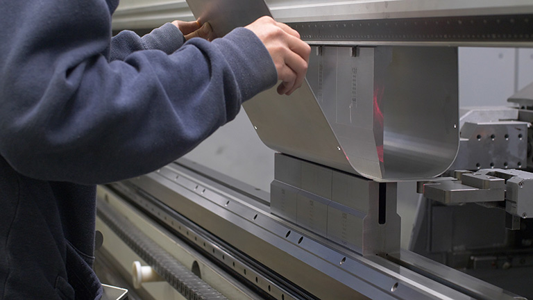
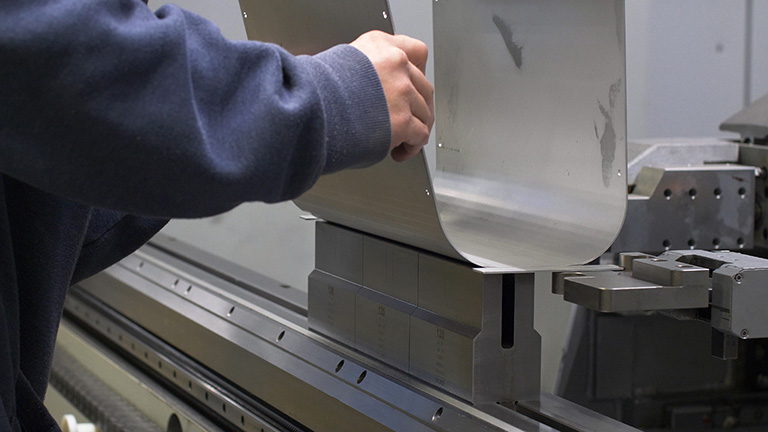
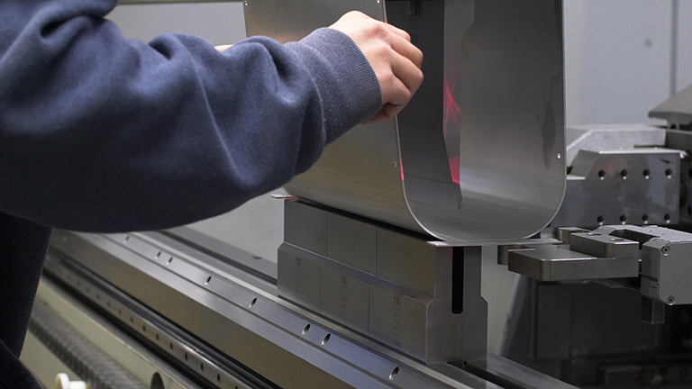
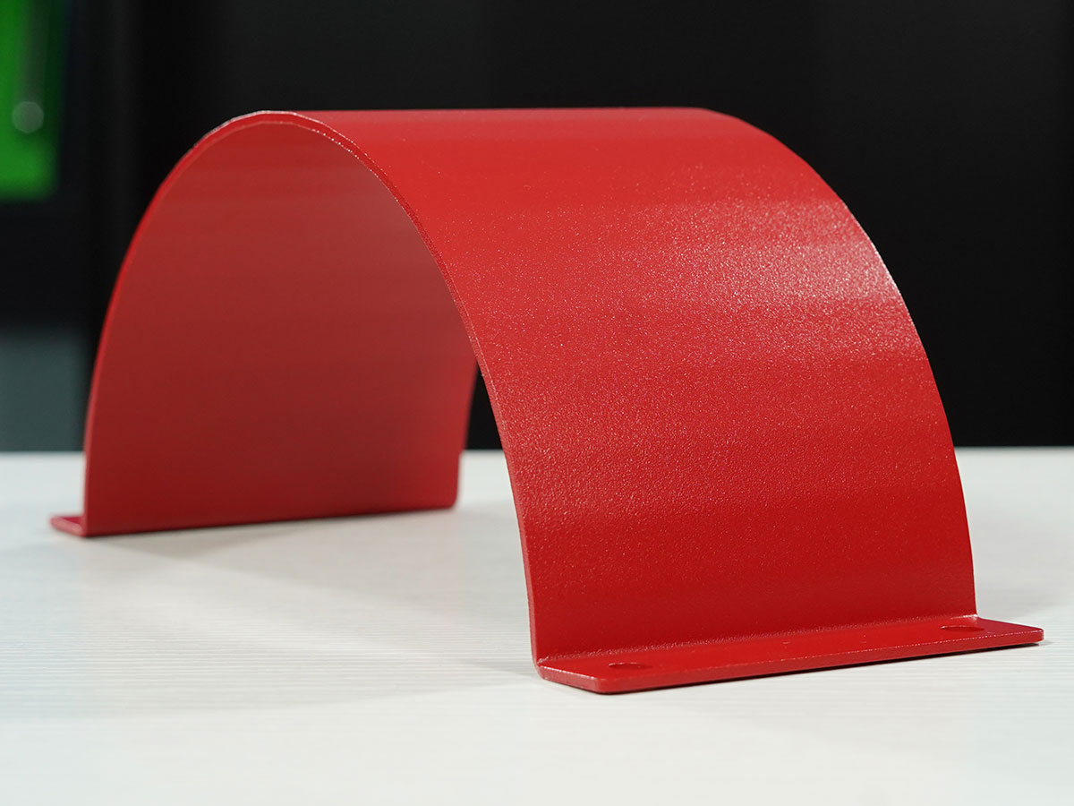
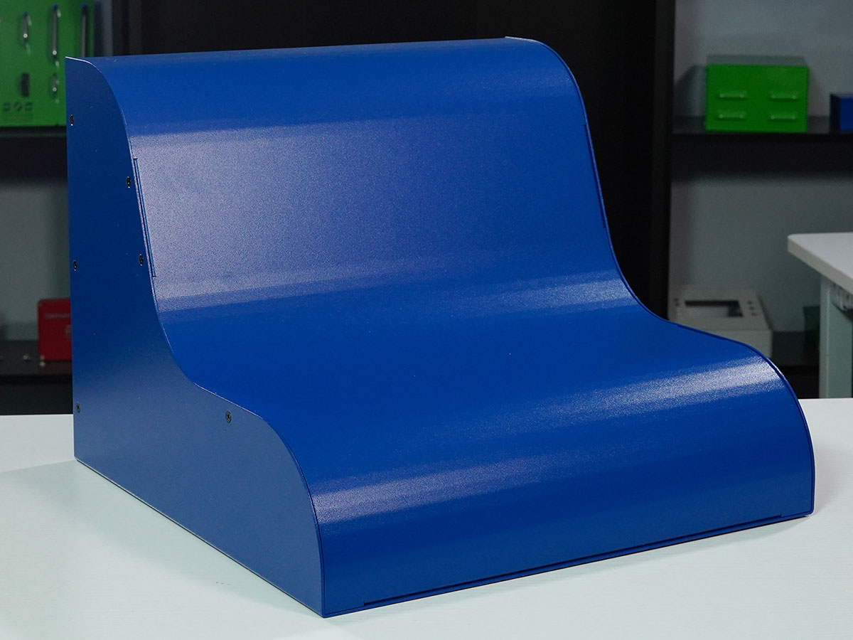
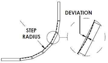
Step bending is the process of taking a large bend radius and dividing it up into multiple smaller bends in order to approximate a larger radius. Our press brake machinery can complete many bends in succession in order to achieve radii of 1.0” or more (so long as size limitations are met).
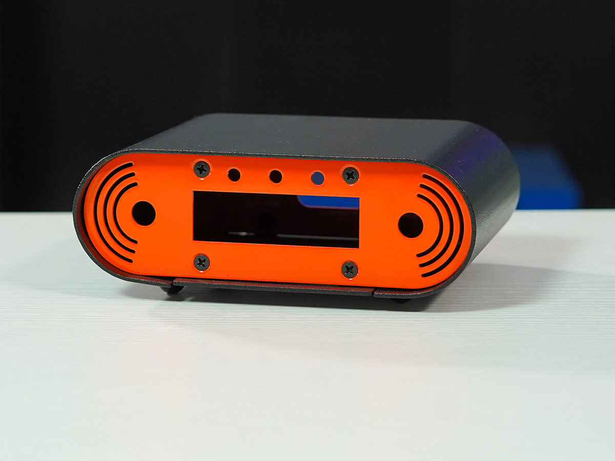
Also referred to bump bending, step bending can be very useful for achieving a curvy look for aesthetic purposes without needing customized tooling.
Materials
We are able to complete step bends on all of the sheet metals we stock, with the exception of two materials:
Perforated Sheet Metal: Since this material is pre-cut with the circular cutouts, the location of the holes are uncontrolled. As a result, we cannot step bend perforated sheet metal consistently.
6061 Aluminum: This general-purpose alloy is well suited for CNC machining, but it is brittle and prone to cracking when bent. 5052 aluminum is the optimal choice for sheet metal fabrication, including step bending.
Material Thickness & Radii
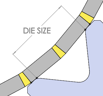
The spacing between step bends is limited by the size of the bending die used. The thicker the material, the larger the bending die must be in order to ensure accurate bending while minimizing wear to the machine and tool.
For the smoothest bending and ideal end result, we recommend minding these values:
| Material Thickness | Die Size | Minimum Step Bend Radius | Nominal Deviation From Radius |
|---|---|---|---|
| ≤ 0.051”| 1.295mm | 0.236" | 6mm | 0.38" | 9.652mm | 0.005" | 0.127mm |
| ≤ 0.064” | 1.626mm | 0.315" | 8mm | 0.61" | 15.494mm | 0.005" | 0.127mm |
| ≤ 0.129” | 3.277mm | 0.630" | 16mm | 2.41" | 61.214mm | 0.005" | 0.127mm |
If you require a smaller radius than minimum mentioned above, contact us to discuss your options.
Size & Radii Limitations
Ultimately, there is no upper limit on the overall bend radius that can be achieved when using step bending. However, certain size limitations will dictate the bend radii that can be achieved:
- Maximum flattened part size is 47”x95” (1193.8mm x 2413mm), as our sheet metal typically comes in 48” x 96” sheets, and our lasers require a 0.5” (12.7mm) space around the perimeter for affixing the sheet to the laser beds.
- Thinner materials that are of the maximum dimension have an increased chance of the material bowing during the bending process
If you a require an enclosure or part with step bends beyond the constraints listed above, contact us to discuss your options.
U-Shape Limitations
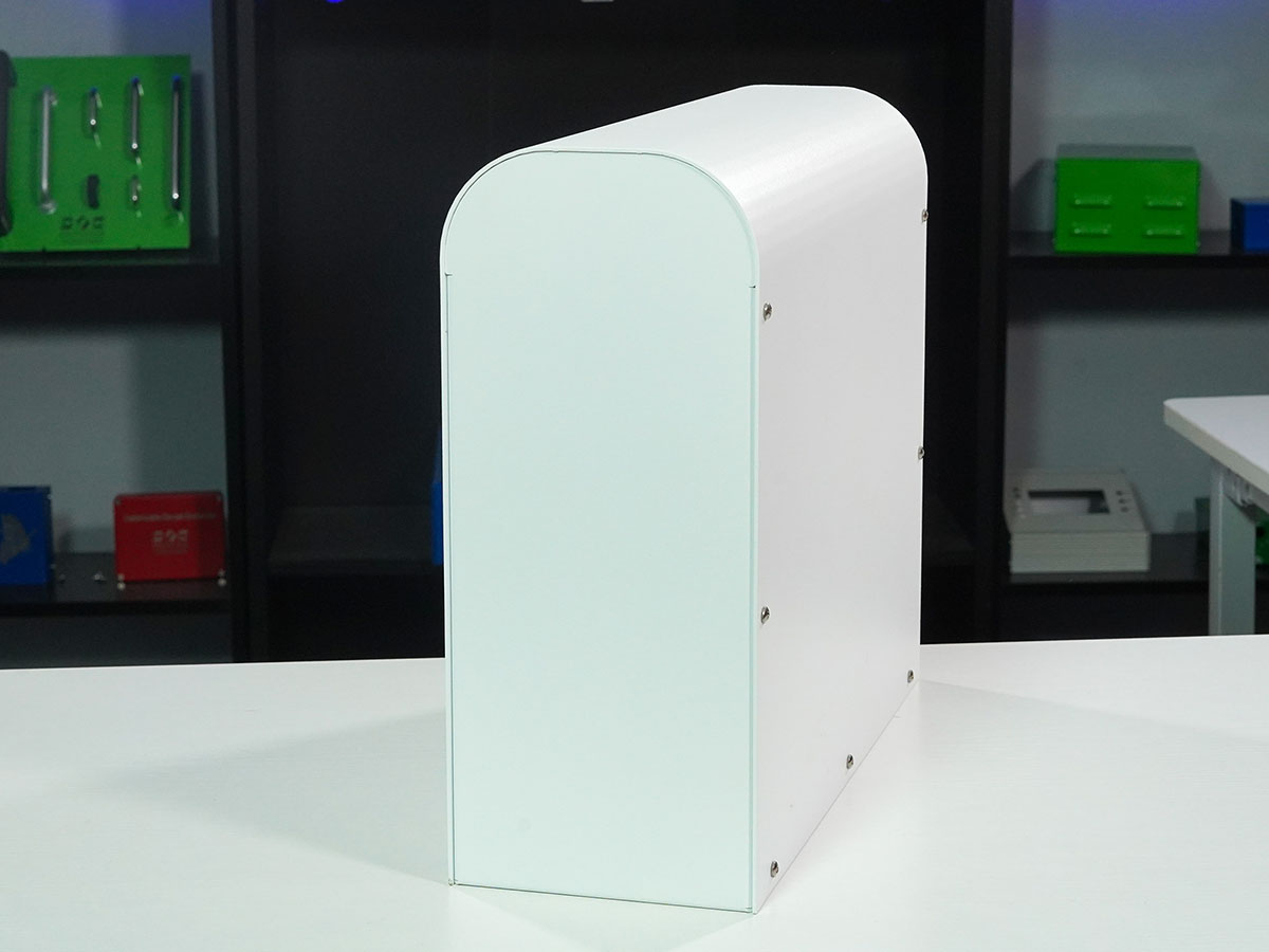
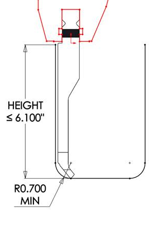
Step bending opens up the possibility of bending U-shaped enclosures that are much taller than they are wide. However, there are some constraints to consider in order to ensure manufacturability:
- If a U-shape profile is 6.1” or less in height, the bend radius should be 0.7” or larger in order to clear the tooling.
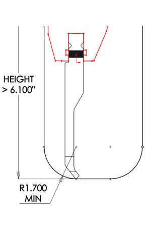
- If a U-shape profile is larger than 6.1” high, the bend radius should be 1.7” or larger in order to clear the ram.
- The middle face will have positioning tabs coming off the sides, ideally there should be about 1” (25.4mm) between the radii to attach these and no flanges bent off this face.
- 180° radii are possible, however, the spacing between each step may need to be larger in order to accommodate the positioning tabs. Our Engineering & Design Services team can assess your design to determine the feasibility.
Ultimately, we are here to create your custom enclosures and parts in a way that will meet your project requirements.
If your designs include large bend radii where step bends will be required and they appear to not meet our minimum limitations listed above, there may be a solution. Contact us to discuss your options.
Holes Within a Bend
Typically, placing cutouts within a traditional bend, or even close to the bend, is not recommended, as the cutouts will stretch and distort. (Learn more about this in our Proto Tech Tip video about minimum bends).
However, the nature of step bends – with multiple smaller bends completed in order to approximate a larger bend radius – allows the possibility of placing circular cutouts (i.e. holes) very close to the bend line, or even within the bend itself.
Two general rules of thumb:
- Circular cutout dimension should be smaller than are equal to 0.250” (6.35mm).
- The cutouts should be widely spaced.
Finishes
Custom parts and enclosures with step bends are able to be finished with virtually any of our finishes, so long as the parts fit within the dimensional constraints and other requirements.
Number of Steps Within a Bend
Contact us to get your design quoted by using our Request-For-Quote to submit your design to your Protocase Account Manager.
Once your part is assessed and quoted by our Engineering & Design Services team, you will be advised on the number of steps within the step bend.
Step Bend Tolerances

The flange size tolerance is ±0.010” (0.254mm) per 10 steps. (minimum ±0.010”)
The angular tolerance is ±1° per 10 steps. (Minimum ±1°)”